Close

Have questions? Log in to access chat
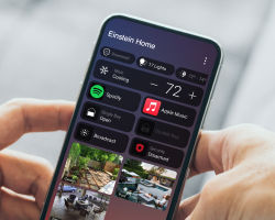
Dive into our most advanced, intuitive, and powerful platform to date, designed to enhance every aspect of the smart living experience.
High-quality solutions for the essentials you need for all your custom installs
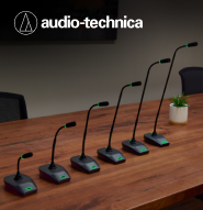
Be heard with Audio-Technica mics and accessories. Experience simple setup, reliable sound performance, and superior voice capture.
.png)
Dedicated lighting wire. We handled the specification, freeing you to focus on other tasks

Strike the balance of performance and value. With user and installer features
Access Networks' A770 and A670 Unleashed Wi-Fi 7 Indoor Access Points offer unprecedented speeds, reduced latency, and even greater network reliability.
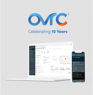
A decade's evolution starts a new era, enhanced with new features.
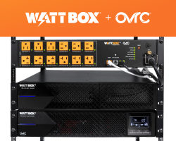
Enjoy zero transfer time to battery, longer run time, and advanced OvrC® features with our Online Double Conversion UPS.

Bring true 4K HDR entertainment to your customers with the latest laser light source projectors from Sony, offering crisp, vibrant HDR images, even in well-lit spaces.
Get full-powered audio that sounds as good as it looks with the latest from Triad®.
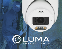
Combining IR Night Vision and Color at Night technology for unparalleled clarity, even in complete darkness. Now featuring Active Deterrence!

Keep customers connected in any space with outstanding outdoor solutions designed to make your jobs easier.

All the installation tools you'll need to terminate Cleerline fiber cable and connectors quickly and cleanly.
Intelligent lighting is an essential part of every smart home and provides added convenience and peace of mind. The Control4 Receptacle Outlet Switch provides an elegant way to invisibly control lamps and other plug-in devices in your Control4 system. It includes one always-on outlet, and one switched outlet for on/off control of virtually every 120V lighting load type, including LED lights, incandescent, halogens, compact fluorescents, and other plug-in devices. Built-in Zigbee allows control through Control4 interfaces, lighting scenes, and programming. It also functions as a repeater, extending the range of the Zigbee network. A button on the front of the outlet allows it to be controlled locally. Available in 8 stylish colors and finishes.
Intelligent lighting is an essential part of every smart home and provides added convenience and peace of mind. The Control4 Receptacle Outlet Switch provides an elegant way to invisibly control lamps and other plug-in devices in your Control4 system. It includes one always-on outlet, and one switched outlet for on/off control of virtually every 120V lighting load type, including LED lights, incandescent, halogens, compact fluorescents, and other plug-in devices. Built-in Zigbee allows control through Control4 interfaces, lighting scenes, and programming. It also functions as a repeater, extending the range of the Zigbee network. A button on the front of the outlet allows it to be controlled locally. Available in 8 stylish colors and finishes.
| C4-V-ROSW120-BI | C4-V-ROSW120-BL | C4-V-ROSW120-BR | C4-V-ROSW120-IV | C4-V-ROSW120-LA | C4-V-ROSW120-MB | C4-V-ROSW120-SW | C4-V-ROSW120-GR | C4-V-ROSW120-WH |
|---|---|---|---|---|---|---|---|---|
Biscuit |
Black |
Brown |
Ivory |
Light Almond |
Midnight Black |
Snow White |
Black |
White |
Receptacle Outlet Switch |
Receptacle Outlet Switch |
Receptacle Outlet Switch |
Receptacle Outlet Switch |
Receptacle Outlet Switch |
Receptacle Outlet Switch |
Receptacle Outlet Switch |
Receptacle Outlet Switch |
Receptacle Outlet Switch |
One pass through (top), one controlled (bottom) |
One pass through (top), one controlled (bottom) |
One pass through (top), one controlled (bottom) |
One pass through (top), one controlled (bottom) |
One pass through (top), one controlled (bottom) |
One pass through (top), one controlled (bottom) |
One pass through (top), one controlled (bottom) |
One pass through (top), one controlled (bottom) |
One pass through (top), one controlled (bottom) |
125V AC, 60 Hz |
125V AC, 60 Hz |
125V AC, 60 Hz |
125V AC, 60 Hz |
125V AC, 60 Hz |
125V AC, 60 Hz |
125V AC, 60 Hz |
125V AC, 60 Hz |
125V AC, 60 Hz |
1000W incandescent; 450W LED/CFL; 1800W (15A) resistive, 1/2 HP motor |
1000W incandescent; 450W LED/CFL; 1800W (15A) resistive, 1/2 HP motor |
1000W incandescent; 450W LED/CFL; 1800W (15A) resistive, 1/2 HP motor |
1000W incandescent; 450W LED/CFL; 1800W (15A) resistive, 1/2 HP motor |
1000W incandescent; 450W LED/CFL; 1800W (15A) resistive, 1/2 HP motor |
1000W incandescent; 450W LED/CFL; 1800W (15A) resistive, 1/2 HP motor |
1000W incandescent; 450W LED/CFL; 1800W (15A) resistive, 1/2 HP motor |
1000W incandescent; 450W LED/CFL; 1800W (15A) resistive, 1/2 HP motor |
1000W incandescent; 450W LED/CFL; 1800W (15A) resistive, 1/2 HP motor |
Total maximum load for both outlets: 1800W (15A) resistive |
Total maximum load for both outlets: 1800W (15A) resistive |
Total maximum load for both outlets: 1800W (15A) resistive |
Total maximum load for both outlets: 1800W (15A) resistive |
Total maximum load for both outlets: 1800W (15A) resistive |
Total maximum load for both outlets: 1800W (15A) resistive |
Total maximum load for both outlets: 1800W (15A) resistive |
Total maximum load for both outlets: 1800W (15A) resistive |
Total maximum load for both outlets: 1800W (15A) resistive |
2.4 GHz (Zigbee IEEE 802.15.4) mesh networki |
2.4 GHz (Zigbee IEEE 802.15.4) mesh networki |
2.4 GHz (Zigbee IEEE 802.15.4) mesh networki |
2.4 GHz (Zigbee IEEE 802.15.4) mesh networki |
2.4 GHz (Zigbee IEEE 802.15.4) mesh networki |
2.4 GHz (Zigbee IEEE 802.15.4) mesh networki |
2.4 GHz (Zigbee IEEE 802.15.4) mesh networki |
2.4 GHz (Zigbee IEEE 802.15.4) mesh networki |
2.4 GHz (Zigbee IEEE 802.15.4) mesh networki |
Up to 45 m (150 feet) line of sight between the switch and the closest receiver module. For normal use, place devices within 4.5 - 9 m (15 - 30 feet) of each other |
Up to 45 m (150 feet) line of sight between the switch and the closest receiver module. For normal use, place devices within 4.5 - 9 m (15 - 30 feet) of each other |
Up to 45 m (150 feet) line of sight between the switch and the closest receiver module. For normal use, place devices within 4.5 - 9 m (15 - 30 feet) of each other |
Up to 45 m (150 feet) line of sight between the switch and the closest receiver module. For normal use, place devices within 4.5 - 9 m (15 - 30 feet) of each other |
Up to 45 m (150 feet) line of sight between the switch and the closest receiver module. For normal use, place devices within 4.5 - 9 m (15 - 30 feet) of each other |
Up to 45 m (150 feet) line of sight between the switch and the closest receiver module. For normal use, place devices within 4.5 - 9 m (15 - 30 feet) of each other |
Up to 45 m (150 feet) line of sight between the switch and the closest receiver module. For normal use, place devices within 4.5 - 9 m (15 - 30 feet) of each other |
Up to 45 m (150 feet) line of sight between the switch and the closest receiver module. For normal use, place devices within 4.5 - 9 m (15 - 30 feet) of each other |
Up to 45 m (150 feet) line of sight between the switch and the closest receiver module. For normal use, place devices within 4.5 - 9 m (15 - 30 feet) of each other |
0° C to 40° C (32° F to 104° F) |
0° C to 40° C (32° F to 104° F) |
0° C to 40° C (32° F to 104° F) |
0° C to 40° C (32° F to 104° F) |
0° C to 40° C (32° F to 104° F) |
0° C to 40° C (32° F to 104° F) |
0° C to 40° C (32° F to 104° F) |
0° C to 40° C (32° F to 104° F) |
0° C to 40° C (32° F to 104° F) |
5% to 95% non-condensing |
5% to 95% non-condensing |
5% to 95% non-condensing |
5% to 95% non-condensing |
5% to 95% non-condensing |
5% to 95% non-condensing |
5% to 95% non-condensing |
5% to 95% non-condensing |
5% to 95% non-condensing |
-20° C to 60° C (-4° F to 140° F) |
-20° C to 60° C (-4° F to 140° F) |
-20° C to 60° C (-4° F to 140° F) |
-20° C to 60° C (-4° F to 140° F) |
-20° C to 60° C (-4° F to 140° F) |
-20° C to 60° C (-4° F to 140° F) |
-20° C to 60° C (-4° F to 140° F) |
-20° C to 60° C (-4° F to 140° F) |
-20° C to 60° C (-4° F to 140° F) |
29 × 44 × 105 mm (1.13 × 1.75 × 4.13 in.) |
29 × 44 × 105 mm (1.13 × 1.75 × 4.13 in.) |
29 × 44 × 105 mm (1.13 × 1.75 × 4.13 in.) |
29 × 44 × 105 mm (1.13 × 1.75 × 4.13 in.) |
29 × 44 × 105 mm (1.13 × 1.75 × 4.13 in.) |
29 × 44 × 105 mm (1.13 × 1.75 × 4.13 in.) |
29 × 44 × 105 mm (1.13 × 1.75 × 4.13 in.) |
29 × 44 × 105 mm (1.13 × 1.75 × 4.13 in.) |
29 × 44 × 105 mm (1.13 × 1.75 × 4.13 in.) |
173 kg (0.38 lb) |
173 kg (0.38 lb) |
173 kg (0.38 lb) |
173 kg (0.38 lb) |
173 kg (0.38 lb) |
173 kg (0.38 lb) |
173 kg (0.38 lb) |
173 kg (0.38 lb) |
173 kg (0.38 lb) |
Color |
Application |
Outlets |
Power Requirements |
Supported Load Types |
Maximum Load |
Control Communications |
Range |
Operating Temperature |
Operating Humidity |
Storage Temperature |
Dimensions (W x H x D) |
Weight |
Control4 warrants its hardware product to be free from defects in material and workmanship during the warranty period. If the hardware proves to be defective in material or workmanship during the warranty period, Control4 will, at its sole option, repair or replace the product with a like product. The warranty extends only to products purchased directly from Control4 Corporation or an Authorized Control4 Dealer. For complete limited warranty information, including details on purchaser legal rights as well as limited warranty exclusions, visit here.
This feature is not currently optimized for mobile devices. We apologize for any inconvenience this may have caused. Please access Keycap engravings from a tablet or desktop computer.


